

To make a badge inscription sit level relative to its pin, align the top of the artwork with the backing position. Centring a circular insert does not do this. Keep the backing in one loading position and assemble a four-mark probe: it will show where to aim the top of the next design.
The centre does not define the top
You can turn a circular insert around its centre without moving the centre itself. An even margin around the edge therefore does not ensure that an inscription will sit horizontally on clothing. Turning the whole finished badge turns both the artwork and the pin: their relative angle stays the same.
Artwork top points up
Pin-axis projection from the back
The arrow marks the top of the artwork. The pin axis is horizontal.
Artwork top points right
Pin-axis projection from the back
The circle has the same centre. The artwork sits at a different angle to the pin.
Schematic front views. The dashed line below each circle is an explanatory projection of the straight part of the pin from the back. The pin is not visible on the badge face. Each arrow stands for artwork with a defined top.
For example, in a two-stage rotary press, a die first picks up the front shell with the paper insert; the backing is then brought to the artwork already held by the tool. These are two separate loading operations. Their reference points and the movement of the dies depend on the construction, so a “to the right” position or a particular angle from another machine's instructions cannot be applied to every press.
A probe that finds the top
First decide how the badge will be worn. In our example, the straight section of the closed pin is horizontal. Also record which side holds the clasp and which holds the loop: a horizontal axis alone allows two positions half a turn apart. A sketch of the fastening on fabric will help you assess every trial in the same position.
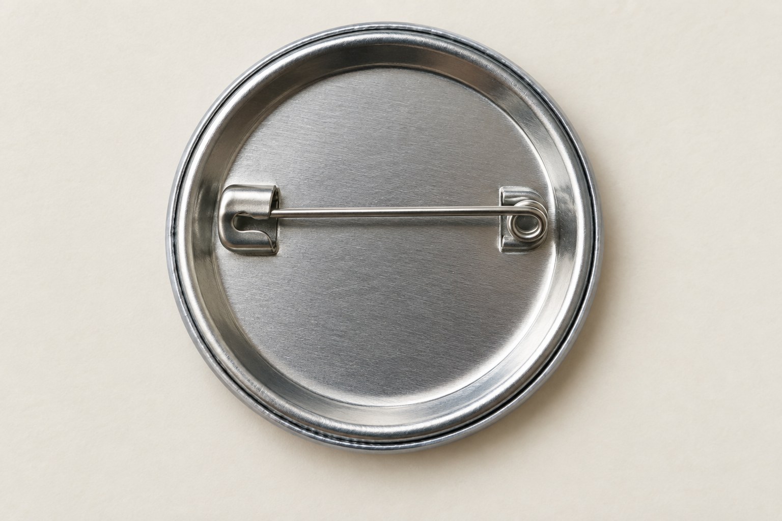
Rear view. The straight section of the closed pin provides a reference; the clasp and loop help distinguish the two orientations.
- Mark a trial insert with А at the top, Б on the right, В at the bottom and Г on the left, inside the part that will remain visible on the finished badge. These same Cyrillic letters identify the marks throughout. Keep the insert size required by your kit. Choose a stationary part of the press as your loading reference and record where А points relative to it.
- Separately sketch the backing's normal loading position, including the clasp position. Repeat it unchanged, along with the sequence of operations. Assemble the probe according to your press instructions; clear hands and any auxiliary objects from the working area before pressing.
- Put the finished badge in the recorded wearing position and look at its front. Find the mark that ended up at the top. That mark's original loading location gives the direction for the top of the next design.
Every diagram uses the same viewpoint: the printed face. “Right” and “left” belong to the viewer looking at the artwork. The diagrams do not switch to a rear view.
Hypothetical result: Б ends up at the top
Suppose that, after assembly, the chosen wearing position puts Б at the top, В on the right, Г at the bottom and А on the left. Follow that same insert, then a second trial with an arrow design.
1 · Load the probe
А at the top, Б on the right, В at the bottom, Г on the left. View the printed face of the insert.
Backing: the same loading position in both trials.
2 · Finished probe
Pin-axis projection from the back
In the recorded wearing position: Б at the top, В on the right, Г at the bottom, А on the left. This is the stipulated result in this hypothetical example.
Backing: the same loading position in both trials.
Б became the top → aim the next artwork top where Б was at loading.
3 · Load the next insert
The letters stay in their original positions. Point the top of the new artwork, represented by the arrow, towards Б — to the right.
Backing: the same loading position in both trials.
4 · Next result
Pin-axis projection from the back
With the same mapping, Б is at the top again. The top of the new artwork reaches the top with it.
Backing: the same loading position in both trials.
All four circles show the printed face. The letters identify the same points on the insert and are typeset upright for readability. They remain as reference marks on the second trial. The pin defines the wearing position; its dashed projection is drawn outside the circle. The diagram traces a hypothetical result, not the movement of press parts.
For the second trial, keep the letters in the same original locations and point the arrow towards Б. In this example, it must point right at loading. With the backing position unchanged and the mapping repeatable, the arrow will point up on the finished badge. Then orient the top of the actual inscription in the same way, remove the reference letters from the production artwork and check an assembled badge with the inscription itself.
The rightward direction follows from this particular hypothetical probe. If a different mark ends up at the top in your trial, use its original location. The diagram does not prescribe a universal 90° turn.
If the top falls between the marks
Four letters help locate a quarter of the circle, but cannot resolve every angle precisely. Add finer numbered ticks to the trial artwork, starting at А and running clockwise as seen from the printed face. Assemble another probe and read the tick at the top of the finished badge. Aim the next artwork top at that tick's original loading location and check the inscription. The scale records an observed result; it does not describe the mechanism's rotation.
A consistent angle or movement between trials?
The top reaches the same place every time
With identical loading, this lets you use the direction you found. Repeat the check with the actual inscription in the recorded wearing position. A consistent angle establishes repeatable orientation; by itself, it does not prove that the entire press is working correctly.
The top reaches a different place each time
A single angular correction cannot fix this. Check whether the insert slips during movement and whether the parts seat and stay in place consistently. Incomplete crimping or poor seating calls for a separate check of the component set and normal assembly procedure. The tilt alone does not identify a specific fault.
Aligning an inscription does not call for dismantling the press, changing its fastenings or forcibly twisting the back of a finished badge. The probe determines the orientation of the next insert; resolve seating issues separately using the instructions for the specific equipment.
Save two reference positions
After a successful trial, keep a short sketch at the workstation showing where the artwork top points at loading and how the backing is placed. Add the fastening position on fabric and the finished control sample. Repeat the probe after changing the component set or workflow. A radially symmetrical pattern can hide rotation, so use an arrow, name or inscription with a clear top for the check.
If you are choosing materials, look in the blanks for pin badges, magnets and keyrings category for a kit specifically containing a backing with a pin. Verify its compatibility with your press and die: the same nominal diameter does not establish this. A magnet or keyring has its own attachment method to use as the orientation reference.